- Home
- About Us
-
- Offer Documents
- Audiovisual AV for IPO
- Group Companies
-
- MOA & AOA
- Business Details
- Terms and Conditions of Appointment of Independent Directors
- Composition of Various Committees
- Code of Conduct of BOD and SMP
- Details of Establishment of Vigil Mechanism / Whistle Blower policy
- Criteria of Making Payments to Non-executive Directors
- Policy On Dealing With Related Party Transactions
- Policy For Determining ‘Material’ Subsidiaries
- Familiarization Programmes Imparted to Independent Directors
- Email Address For Grievance Redressal
- Shareholding Pattern
- Disclosure of The Policy For Determination of Materiality of Events or Information
- Dividend Distribution Policy
- Annual Returns
- Other Disclosures
- Financials and Reports
- Investor Contact
- Policies
- Announcement
- Corporate Governance
- Contact Us
TMT Bar & Billets
Manufacturing Process after backward integration
Set forth below is a description of the manufacturing process of producing billets from scrap per our backward integration project.
Raw Material
The ideal quality of raw material in case of induction furnace is clean, shredded scrap of low carbon content, sponge iron and melting.
Charging and Loading of Raw Material into Furnace
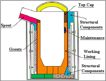
The induction furnace is prepared by lining its inside with ramming mass. The raw materials (stored near the furnace for ease of operation) are weighed in the right proportion and charged (loaded) into the furnace by using an electro magnet attached to an Electric Overhead Traveling Crane (called EOT crane), which ensures quick loading of sizable quantities of materials. The EOT crane increases operator safety and decreases the need and dependence on manpower. (Grab/magnet and Hydraulic trolley, Scrap bundling- 1 cubic meter around 700 kg)
Melting Process
The charge mix is melted in the Induction furnace. A solid state generator converts A.C. Power into D.C. Power, which is converted to A.C. Power of higher frequency (250 to 500 Hz) using thyristors (electronic device). This high frequency (250 to 500 Hz) current is passed through capacitor rack (to achieve the desired constant voltage) through copper Bus Bar into molten bath having water-cooled copper coil, which transfers the heat energy into mixture and melts the charge mix at around 1550°C.
The components in the mixture are melted by heat generated by eddy currents induced by a magnetic field set up by a high frequency alternating current which passes round water-cooled coils surrounding the crucible. The eddy currents increase with the square of the frequency, and an input current between 250 to 500 hertz is employed. As the frequency increases, the eddy currents tend to travel nearer to the surface of a charge (skin effect). The heat developed in the charge depends on the cross-sectional area which carries current. Large furnaces use lower frequencies to get adequate current penetration. The temperature of the metal bath can be adjusted by changing the power input, thereby ensuring proper mixing of components in the melt. The current induced in the molten metal causes a rapid stirring action and helps in melting the rest of charge by washing molten metal against the solid scrap. Thus, the uniformity of mixing the charge is assured and necessity of any manual stirring is avoided. The reactive slag impurities such as silica also attains the same temperature and floats on top, preventing oxidation of the melt. As the charge melts, the level inside the furnace drops and additional charge is added only until the melt reaches 67% of the crucible height. We propose to install a radio remote controlled scrap poking system to push the scrap into the furnace during the melting operation. This will improve the productivity, efficiency and safety of operation. We also are installing a stationary crane on the furnace platform to improve scrap charging and to save power.
Heating is continued till the entire metal mass melts to liquid state. At this stage, a sample of the molten mixture (called “melt”) is sent to the laboratory for analysis. Based on the analysis report, ferro alloys and other materials are added in appropriate quantities and the carbon content is increased or decreased as needed. This process is repeated till the desired composition is achieved. The temperature of the molten metal is checked by immersion pyrometer, and it is transferred to ladles for pouring into billets or desired shapes by continuous casting process. As the level inside the furnace falls, additional mix is poured from top and the cycle repeated without break (to avoid metal solidification, after which the refractory brick lining will have to be replaced and there will be great heat loss). The molten metal is poured with the hydraulic system in the preheated ladle after adding certain fluxes so that the temperature is maintained at about 1600 degree Celsius.
Continuous Casting Process
In the continuous casting process, the melt is solidified into a "semi-finished" billet, bloom, or slab, which immediately goes for rolling to the finishing mills. Continuous casting results in improved yield, quality, productivity and cost efficiency by great saving in heating and storage costs. It also provides increased process control through automation.
To start the casting operation, a dummy bar is inserted into the mould’s outlet at the bottom to seal it. Pulling the dummy bar downward results in the withdrawal of the cast strand (flow of molten metal), which is collected in the ladle. Molten metal is tapped into the ladle from furnaces. After undergoing any ladle treatments (such as alloying and degassing), and checking the temperature, the ladle is transported to the top of the casting machine. Usually, the ladle sits in a slot on a rotating turret at the casting machine; one ladle is 'on cast' (feeding the casting machine) while the other is kept ready and moved to the casting position after the first ladle is filled and moved.
From the ladle, the melt is poured into moulds via the tundish, taking great care to prevent contact with the air (the tundish is the last metallurgical vessel through which molten metal flows before solidifying in the continuous casting mould). When molten metal moves through the tundish, it interacts with refractories, slag, and the atmosphere. Thus, proper tundish design and operation are important for delivering steel of strict composition and quality. The tundish allows a reservoir of metal to feed the casting machine while ladles are switched, thus acting as a buffer of hot metal, as well as smoothening out flow, regulating metal feed to the moulds and cleaning the metal. The tundish is mounted on tundish car which transfers the tundish from a parking station to casting position. Metal is drained from the tundish through another shroud into the top of an open-base water-cooled copper mould which oscillates vertically (or in a near vertical curved path) to prevent the metal sticking to the mould walls. A lubricant (powder or liquid) is also added to the metal in the mould to prevent sticking and to trap any remaining slag particles (including oxide particles or scale) and bring them to the top as a floating layer of slag.
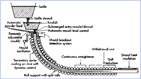
The strand coming out of mould is immediately supported by closely spaced, water-cooled rollers; these support the walls of the strand against the ferro-static pressure of the still-solidifying liquid within the strand. To increase the rate of solidification, the strand is also passed through a spray-chamber and sprayed with large amounts of water. Final solidification of the strand (including core) takes place after the strand leaves the spray-chamber. In each strand, one hot billet shearing machine should preferably be installed to ensure that billet being cast are cut to the desire length by consuming minimum time and in line with the casting speed without causing any loss of metal and also without creating any distortion in the end of the billet so that, the ends of the billet do not cause any adverse impact at the entry of first pass.
After exiting the spray-chamber, the strand passes through straightening rolls and withdrawal rolls. There may be a hot rolling stand after withdrawal to pre-shape the final strand while the metal is still hot. Finally, the strand is cut into predetermined lengths by mechanical means, marked for identification and either taken to a stockpile or the next forming process. The CCM is likely to operate 24 hours whereas rolling mill will require at least 2 hours of maintenance time. Therefore, for accommodating the material cast during this rolling mill shutdown period; the cast billet should be conveyed to the cooling bed for which a sufficient length cooling bed should be provided. It is important to take into consideration the available melting facilities and re-rolling facilities capacity.
Manufacturing Process
We currently manufacture TMT Bars from purchased billets to produce TMT Bars as described below. Once our backward integration project is completed, we will produce our own billets for our TMT Bar production.
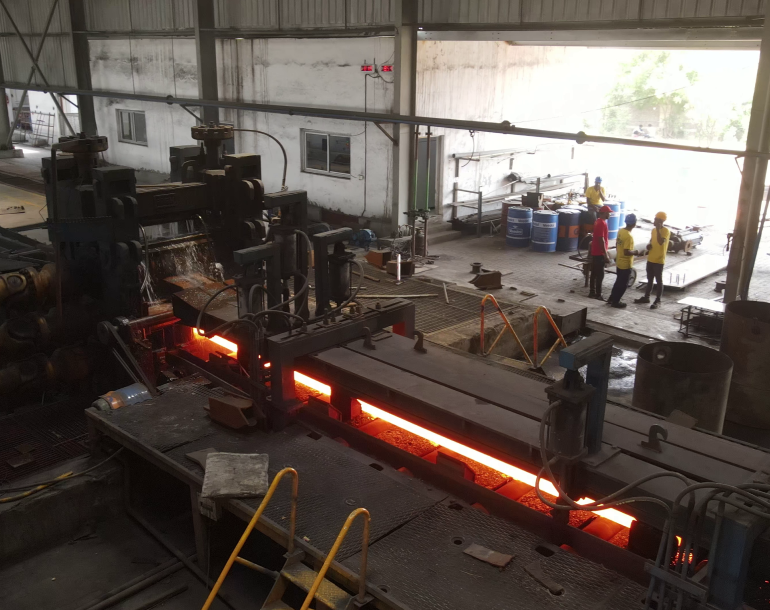
Billets travel from continuous casting machine to roughing mill through the cooling bed. The roughing mill is where most of the elongation is done and the area cross section gradually decreases and the length increases. But the billet is still in the heated state and it continuously moves on to the next rollers through the guideways. To move the hot billet to the next rollers some accelerators are placed at certain intervals. These are called pinch rolls. There are springs on these pinch rolls which puts the pressure on the moving rod. The guideways help the tip of the red hot rod to enter the next roller that is the intermediate mill.
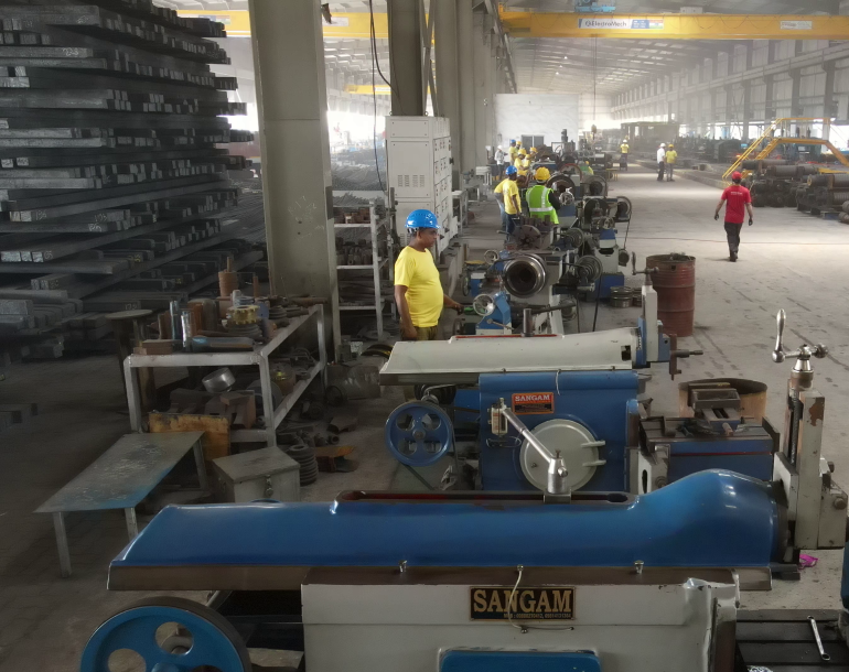
After passing through the roughing mill, the rod is led into the intermediate mill. There is a speed increaser placed for the smooth movement of the rod as the motor is incapable of giving the entire push to the rod. After the intermediate mill, two pinch rolls and a shearer is placed before the finishing mill to make the movement of rod smooth. There are front and back cutters which remove the front and back tip of the hot rod to allow proper entering into the finishing mill.
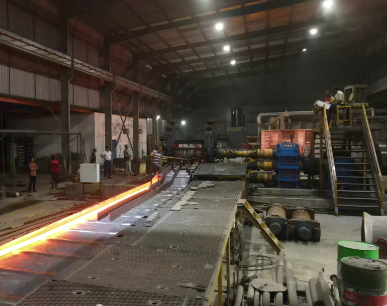
The finishing mill is the main roller where the required dimension is obtained. The rollers are made with precision and in such a way that the exact dimension can be obtained. Quality is of great importance, since the manufactured products are graded and approved by the Indian Standards Institute or Bureau of Indian Standards. The final dimensions of the TMT Bar are achieved by finishing rollers. The rods, after passing through the finishing rollers, are still soft due to high temperature. There is a special guide way present after the finishing rollers which lead the rods to the TMT box. Cantilever stand for the finished mill which improves the quality of the roll with tensile roll.
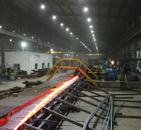
One of the most important parts of the plant is the TMT box where all finished stand TMT are passed through. When the hot reinforced bar leaves the final rolling mill stand, it is instantaneously quenched – a type of heat treatment where the bars are rapidly cooled by water in a quenching box to obtain certain material properties. Quenching prevents the occurrence of undesired processes such as phase transformations etc. It accomplishes this by reducing the time frame during which these undesired reactions have a higher chance of occurring. Apart from it, the sudden drastic change in temperature toughens the outer layer of the steel bar, thus enhancing its tensile strength and durability. Thus, the quenching converts the outer surface of the reinforced bar to Martensite, a hard form of steel and causes it to shrink, which in turn pressurizes the core, thus helping it to form the correct crystal structures. As a result of this process, the surface of the quenched bar becomes cold and hardened, while the core remains hot.
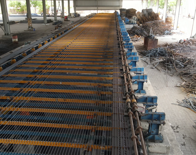
After the self-tempering process, the bars are subjected to atmospheric cooling to equalize the temperature difference between the soft inner core and the hardened exterior.
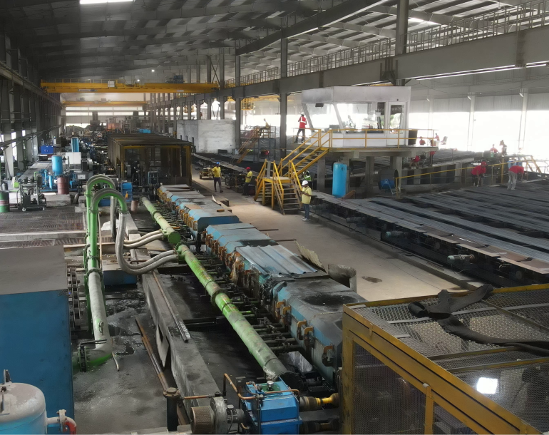
After leaving the quenching box, a temperature gradient is formed through the cross-section of the quenched bar. As a result, heat flows from the core, as it is at a relatively higher temperature to the outer surface. This causes the correct tempering of the outer martensitic layer into a structure called Tempered Martensite and the formation of an intermediate ring of Martensite and Bainite (a plate-like microstructure). The core still stays in the austenitic (a typical cubical crystalline structure, commonly called as gamma-phase iron) state at this stage.
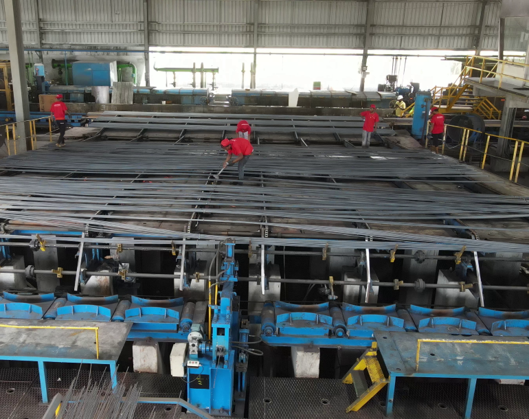
TMT bars forming are generally divided into shearing, bending and threading. The steel bar cutting production line adopts computer control technology, which ensures cutting of steel bar by auto-sizing.
After cutting off by flying shear, the steel bar is moved to the designated storage rack and stored according to the specifications.

Billets travel from continuous casting machine to roughing mill through the cooling bed. The roughing mill is where most of the elongation is done and the area cross section gradually decreases and the length increases. But the billet is still in the heated state and it continuously moves on to the next rollers through the guideways. To move the hot billet to the next rollers some accelerators are placed at certain intervals. These are called pinch rolls. There are springs on these pinch rolls which puts the pressure on the moving rod. The guideways help the tip of the red hot rod to enter the next roller that is the intermediate mill.

After passing through the roughing mill, the rod is led into the intermediate mill. There is a speed increaser placed for the smooth movement of the rod as the motor is incapable of giving the entire push to the rod. After the intermediate mill, two pinch rolls and a shearer is placed before the finishing mill to make the movement of rod smooth. There are front and back cutters which remove the front and back tip of the hot rod to allow proper entering into the finishing mill.

The finishing mill is the main roller where the required dimension is obtained. The rollers are made with precision and in such a way that the exact dimension can be obtained. Quality is of great importance, since the manufactured products are graded and approved by the Indian Standards Institute or Bureau of Indian Standards. The final dimensions of the TMT Bar are achieved by finishing rollers. The rods, after passing through the finishing rollers, are still soft due to high temperature. There is a special guide way present after the finishing rollers which lead the rods to the TMT box. Cantilever stand for the finished mill which improves the quality of the roll with tensile roll.

One of the most important parts of the plant is the TMT box where all finished stand TMT are passed through. When the hot reinforced bar leaves the final rolling mill stand, it is instantaneously quenched – a type of heat treatment where the bars are rapidly cooled by water in a quenching box to obtain certain material properties. Quenching prevents the occurrence of undesired processes such as phase transformations etc. It accomplishes this by reducing the time frame during which these undesired reactions have a higher chance of occurring. Apart from it, the sudden drastic change in temperature toughens the outer layer of the steel bar, thus enhancing its tensile strength and durability. Thus, the quenching converts the outer surface of the reinforced bar to Martensite, a hard form of steel and causes it to shrink, which in turn pressurizes the core, thus helping it to form the correct crystal structures. As a result of this process, the surface of the quenched bar becomes cold and hardened, while the core remains hot.

After the self-tempering process, the bars are subjected to atmospheric cooling to equalize the temperature difference between the soft inner core and the hardened exterior.

After leaving the quenching box, a temperature gradient is formed through the cross-section of the quenched bar. As a result, heat flows from the core, as it is at a relatively higher temperature to the outer surface. This causes the correct tempering of the outer martensitic layer into a structure called Tempered Martensite and the formation of an intermediate ring of Martensite and Bainite (a plate-like microstructure). The core still stays in the austenitic (a typical cubical crystalline structure, commonly called as gamma-phase iron) state at this stage.

TMT bars forming are generally divided into shearing, bending and threading. The steel bar cutting production line adopts computer control technology, which ensures cutting of steel bar by auto-sizing.
After cutting off by flying shear, the steel bar is moved to the designated storage rack and stored according to the specifications.
Grades of TMT Bars
The TMT Bars are graded on various compositions. The TMT bars are made of these compositions determine the various characteristics of TMT bars such as malleability and hardness, The following is the chemistry of the steel used to produce TMT bars:
| Parameter | Fe415 | Fe500 | Fe550 | Fe415D | Fe500D |
|---|---|---|---|---|---|
| Carbon | 0.30 | 0.30 | 0.30 | 0.25 | 0.25 |
| Sulphur | 0.060 | 0.055 | 0.055 | 0.045 | 0.040 |
| Phosphorus | 0.060 | 0.055 | 0.055 | 0.045 | 0.040 |
| Sulphur & Phosphorus | 0.110 | 0.105 | 0.100 | 0.085 | 0.075 |
| CE | 0.42 | 0.42 | 0.42 | 0.42 | 0.42 |
Usage of TMT Bars
| TMT Bars | |
|---|---|
| Section (mm) | Usage |
| 8 MM | 8 MM TMT Bar is mainly used in construction. It is used for making rings which are attached or fitted in pillar structure and linter structure. It helps in providing the support to pillar structure or Linter Structure in the process of construction. |
| 10 MM & 12 MM | 10 MM & 12 MM TMT Bars which are used for building up of roof top in RCC slab which is recommended for carrying heavy Loads in many RCC structure such as Columns, Beams, Slabs, Cantilever etc. |
| 16 MM | 16 MM TMT Bar is mainly used for construction that is Ground Floor plus one and above. For such type of construction, 16 Mm TMT bars are recommended to bear the load of upper floors. |
| 20 MM, 25 MM and 32 MM | 20MM, 25MM & 32 MM TMT bars are advised for bringing up the Foundational work stronger, the thickness of such rods provides more grip that sustains the load of the Upper Floors. Such bars are taken up for construction of huge projects. |
